"Top-down doesn't work", quoting from Arlen Nipper, President and CTO of Cirrus Link, speaks at Advantech 2016 Industrial IoT World Partner Conference. Youtube Link
The following MQTT Broker application structure is from GTWang Blogger. I think this structure delivers a clear spirit of MQTT that is M2M, Device to Device, Tag to Tag communication. It is a flat structure and just like Arlen said, Top-down doesn't work, because there is no master-slave or top-down relation in it.

The Origin of MQTT
MQTT(Message Queuing Telemetry Transport) was invented by Andy Stanford-Clark (IBM) and Arlen Nipper (Arcom, now Cirrus Link) back in 1999, when they faced AT&T regulation issue and turned to VSAT(satellite communication) solution to get data and control oil pipeline system. However, they could not use the traditional way to poll devices thru satellites due to data cost expensive and propagation delay.

MQTT Benefits - Do More With Less
MQTT is invented for SCADA application 20 years ago. It becomes popular in these years due to IoT and Cloud computing. The key of being one of the hottest IoT language is the need for real-time, QoS(Quality of Service, makes sure Subscriber receive msg), lower power consumption, light-weight protocol. It must be the reason why FB Messenger adopts MQTT protocol. And it is a great example of "Do More With Less". Company can create various applications and product thru MQTT benefits.
SCADA Application
Back to the original invention for SCADA system, an application interface to control and get data from PLCs and other sensor device nodes. This structure has been no change for almost 40 years.
Is it the time to do something different for SCADA?
According to Arlen, "What we know Top-Down doesn't work". It seems like that they already used Top-Down method, from IT(Information Technology) to OT(Operation Technology) for controlling and monitoring pipeline system and the result was negative. It comes the conclusion, "Bottom-Up" is a good way to implement MQTT for SCADA application.
In 1999, I believe that there was no MQTT supported PLC or sensor devices. Even there was, it had to be highly-customized product and cost expensive in the market.
Nowadays, MQTT is an open protocol, and so many device can implement MQTT for various applications. It should be a good timing to do "Bottom-Up", from OT to IT, for SCADA application by implementing MQTT.
MQTT Implementation for SCADA - 欲練神功 引刀自宮
Traditional SCADA system hooks up devices tightly for one single application purpose. When it transforms to MQTT bases, all devices need to be decoupled from each others. And then IT engineer can integrate data from MQTT to create OT SRP(Solution Ready Package). This is a big transformation to break up original SCADA design and then to grow up applications with MQTT spirit in it.
1. Demodulation is the first step to do MQTT.
2. Create OT solution.
Picture from Youtube video

Hands-On MQTT
In the following section, it shows you how easy it is to build MQTT connection between iPhone, NB and Raspberry Pi.
Prepare
1. Install MQTT on Raspberry Pi. Refer to the detail and great instruction already post by
https://blog.gtwang.org/iot/raspberry-pi/raspberry-pi-mosquitto-mqtt-broker-iot-integration/
Install: apt-get install mosquitto mosquitto-clients
Subscribe: mosquitto_sub -t test
Publish: mosquitto_pub -t test -m "Hello, world!"
2. Install MQTT Broker on PC NB. This is easier for monitoring MQTT msg communication thru Windows interface.

3. Install MQTTT app on iPhone

Testing
1. Open App in iPhone, Enter Broker IP address and Subscribe a topic.


2. Open MQTTlens in Chrome app and add Connection

3. Enter MQTT Broker IP address

4. Subscribe a topic and Publish it to test whether it works or not on this NB


5. Check iPhone MQTT msg


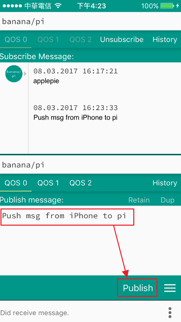
7. Try push msg from iPhone to Pi and check Pi msg in terminal.

8. Push msg from Pi to Phone


Conclusion
With free open source MQTT, the communication between devices is really a piece of cake. After reading this article, you could have a better idea about MQTT and how to test it in just a few minutes. It gives you more time to create applications instead of spending effort on communications problem.
As for SCADA system, is a flat structure with decoupled devices doable in SCADA? I think we need more time and cases to prove it.
留言
張貼留言